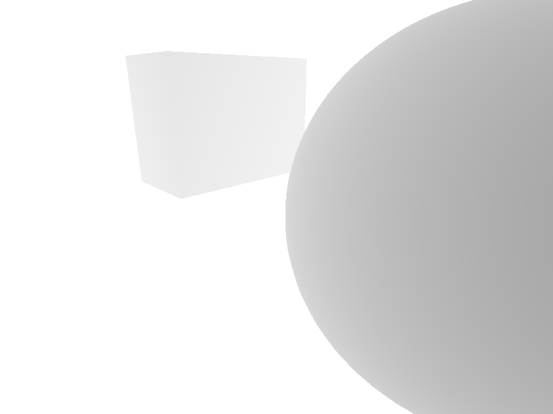
- 4 objects (1 lamp, 2 spheres and 1 plane)
- 34,378 triangles (1 sphere has no triangles, ask OBJ file)
- 640x480 = 307,200 pixels
giving us more than 10.5 billion queries for a single rendered scene. In general a CPU has 1-2 GHz in a single thread. That means one thread can calculate around 1-2 billion steps per second.
Nowadays a CPU can have multiple cores (mine has 4 cores with each 2 threads). I could use multithreading to calculate the color of i.e. 8 pixels at the same time, but I suggest to avoid that complicated architecture, and that for 3 reasons:
- It needs correct locking when several threads try to access the same memory
- Some of you (beginners) might not be familiar with multithreading and locking
- Debugging the code will become more than difficult and makes algorithms more difficult to read and analyze
Possible speed ups without multithreading
Saying that it means we need another solution to speed up raycasting (and raytracing). I found a few possible ways to accelerate our render process without multithreading and multiprocessing, but we will include only one of them in our framework (maybe I'll add the others later too). We will start with the most complex one and go step by step to the simplier methods.
Bounding sphere
This was my first solution: Our objects store all points in a list. the bounding sphere places itself so that all points are enclosed by a sphere (see graph here). We already discussed ray/sphere intersections, and we know that the calculation is done with a single formula.
Only if the bounding sphere is hit by the ray, the list of stored triangles will be searched for the closest triangle. That way we can avoid many many queries if the ray isn't even close to the object.
The big disadvantage of bounding spheres is the correct placement of center and radius. All developed algorithms are approximations and provide an error coefficient. In other words it is quite impossible to calculate the perfect sphere with the smallest radius to cover all points in question.
Bounding Box
Like the bounding sphere it encloses all points in question. A box has 8 points and 6 surfaces, which means we have more queries to figure out if the ray intersects with the box, especially if the box is also rotated and scaled by transform algorithms. Finding the correct sizes is also quite difficult.
Binary Space Partitioning (BSP)
A BSP seperates a space into two subspaces, and these subspaces in another two subspaces and so on. Therefore the area to search an object gets smaller and smaller, partitioning points and triangles into certain areas.
The difficult part of that is the implementation of good seperators.
Axis-Aligned Bounding Box (AABB)
This is the simple version of the regular bounding box. Like the name already says, each surface is aligned to the 3 axis x, y and z. The center is the average value of the minimal and maximal values for each axis, and the difference of these values are the bounding sizes.
There are two ways to describe an AABB:
- Using a point for minimal values and a point for maximal values
- Using a center and a vector describing the (minimal) distance from center to surface
Even the calculation for ray/AABB intersection is a lot simplier than that of a bounding box, and it serves as the foundation of the data structure we will use in the framework.
Octree
Imagine an AABB. Now half all 3 sizes (x, y and z). You get cube which can fit in the original cube eight times.
An Octree is a cube which has 8 sub cubes inside, and each sub cube has another 8 sub cubes (that would be 64 sub cubes in total). This way we have a hierarchy of nodes to store informations. If we hit the big cube, we search for the sub cubes if the ray would hit them, and search even deeper into going smaller cubes. The number of possible points/triangles get smaller and smaller, so that we don't have to look into the whole list.
This data structure is called partitioning tree. It seperates data into sub sections helping us to find the correct data even faster than looking into the whole list.
Almighty Octree
The most important thing about an axis-aligned bounding box is that it surrounds the whole object (i.e. a sphere). We do that by getting min and max of x, y and z. To ensure that all points are inside that box we add the border by ε.


This alone would improve our raycasting. Only when the ray intersects with the AABB we go through the list of triangles and search for the closest triangle hitting that ray. But a sphere can have thousands or millions of triangles, We don't have time to look into all of them.
The advantage of that AABB is that we can half the size of all x, y and z and seperate it into 8 smaller sub AABBs. Here is what I mean:

These sub AABBs can be divided into another 8 sub AABBs and so on. The advantage of that is that we can decide the creation of a sub AABB (let's call them node like for binary trees). If there is a node, than there is at least one data set to expect.
Unfortunately memory storage would increase exponential (S(23n)). We can't go into infinite depths. Instead of saying one child node can only have one triangle we can have one node have a limited number of triangles. If that limit is exceeded, then split all triangles into appropriate child nodes.
Sometimes a triangle can exist in several sub nodes (cause of its size). Let's say an object has 5000 triangles: The octree might have 5010 triangles or even more. That way we can avoid cross queries to other nodes of the same level.
Optional you can make an Octree as perfect cube of size a, but I suggest to make it of size width, height and depth instead of a single size. a would be the maximum width, height, depth.
Add triangle to Octree
My suggestion is the following algorithm:
- If limit is not reached OR node reached max depth
- Add triangle to list
- If that triangle exceeds limit and max depth is not reached
- Query all stored triangles for intersection with sub nodes
- Create sub node if there is no node for that position
- Tell node that limit is reached
- Otherwise add triangle to sub nodes (more fitting nodes possible)
- Create sub node if there is no node for that position
Triangle/AABB intersection test
The big question is when does a triangle intersect with an AABB? Tomas Möller suggested a very fast algorithm which can answer our problem (paper). He implemented the Separating Axis Therom (SAT) to ask 3 questions in 13 tests:
- Is there at least one triangle point inside AABB? (True if there is)
- Does the plane overlaps with AABB? (True if there is)
- Is there a separating plane between triangle edge's and plane's normal (False if there is)
I modified the algorithm so that instead of overlapping test (Test 2) I query if there is a triangle edge intersecting with AABB.
Ray/AABB intersection test
This test is quite simple if you remember ray/plane intersection test. For that we need 6 calculations with 2 points: The point with only minimum values and the point with only maximum values.
Once again, here is the formula for ray/plane intersection:
where t is the scalar distance according to ray's starting point S and direction v, P0 is one of the corner points of AABB plane (Pmin or Pmax) and n is the AABB plane's normal. This normal is either (1,0,0), (0,1,0) or (0,0,1) considering the plane in question.
Let's say we want to take the front plane, then n would be (0,0,1) and we need Pmin. Our formula can be shortened as

For the planes front, left and bottom we can use Pmin and for the planes back, right and top we can use Pmax. This makes six calculations. Easy, isn't it?
With that we get six different values for t. We put this into our ray equation to get a point which is exactly on the plane, but is it within the boundary too? If you used the calculation for the front plane, you need to query x and y values if it is inside AABB plane. You get the boundary values from Pmin and Pmax.
If both queries are true, than the ray intersects with the plane and therefore with the whole AABB.
Let's say we want to take the front plane, then n would be (0,0,1) and we need Pmin. Our formula can be shortened as
For the planes front, left and bottom we can use Pmin and for the planes back, right and top we can use Pmax. This makes six calculations. Easy, isn't it?
With that we get six different values for t. We put this into our ray equation to get a point which is exactly on the plane, but is it within the boundary too? If you used the calculation for the front plane, you need to query x and y values if it is inside AABB plane. You get the boundary values from Pmin and Pmax.
If both queries are true, than the ray intersects with the plane and therefore with the whole AABB.
Framework
I explained that I won't change object settings in Scene3D to compare rendering time. But I used the time to make some structure improvements:
- Scene3D:
- Offers option to build Octrees for each object
- All lists are std::maps now for Object3D, Light, Material and Texture
- Uses "keys" to get objects, but can still be turned into std::vector
- That way, objects created from OBJLoader can be transformed easily
- Object3D:
- Contains the new implemented Octree object linked to that object
- ray intersection queries if there is an octree (not null)
- if not, go through each Surface3D like before (makes octrees optional)
- Now has an ID to better identify objects (i.e. when Octree is updated)
- Octree:
- From Object3D instance calculates center and size of AABB
- Creates OctreeNode as root node with prepared informations
- OctreeNode:
- Has 8 child nodes of type OctreeNode
- Stores center, size and 8 childCenters as Vector3D
- contains a list of stored Surface3D if limit or max depth is not reached
- static values for max level and limit valid for all nodes and sub nodes.
- OBJLoader:
- Can now read .obj and .mtl files from different folders
- saves file path so that it can find MTL file
- main.cpp:
- Added timer to see rendering time in seconds
Once again, let's summarize the previously rendered scene
- 4 objects (1 lamp, 2 spheres and 1 plane)
- 34,378 triangles (1 sphere has no triangles, ask OBJ file)
- 640x480 = 307,200 pixels
Time without octrees:
around 8 minutes
Time with octrees
7-8 seconds
To answer your question: I still don't use graphic libraries and therefore no graphic card. BUT I have Intel i7 inside (4 cores/8 threads with 2.4 GHz each). So the result might differ from computer to computer.
Conclusion
We added a data structure into our framework limiting the number of queries for each pixel, and were able to reduce time by around one fiftieth (1:50). And we still didn't (and will never) add multithreading into the framework.
In the next issue we will make a bit of a better rendering scene using extern OBJ files (maybe your creations) and implement the long waited RAYTRACING where we will simulate reflection (mirror) and refraction (glass). We will also make a small introduction into shadowing to make everything a bit more realistic.
Well, see ya in the next issue.


